

|
|
Site map :
Last upgrade to the site:
There has been
This is an unofficial LEGO® web site. Copyright 1996, 2000, Denis Cousineau
|
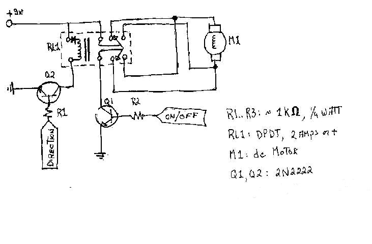
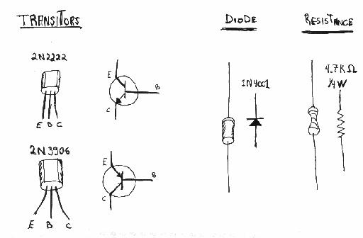
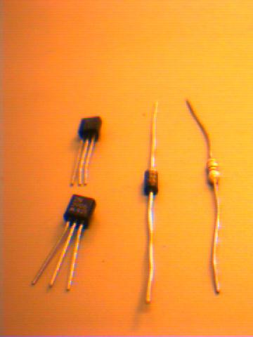
In order to create the circuitry below, you need a computer software that will control your parallel port. (see Program button above). If you are not very familiar with electronic, I *STRONGLY* recommend that you buy an old cheap parallel port card –or even an old computer– , just in case you make a short-circuit. It happen to me twice... You need to buy a few electronic pieces, described in a drawing and pictured in here. Also needed are a few mounting pieces, pictured here. It will cost you about 30 US$. For example, a transistor (model number 2N2222) costs ~50¢, a DPDT relay, ~1.75$ (this is maybe the most expensive piece, you need 7).
The schematic uses a DPDT relay to implement a H-bridge for bi-directional control of one DC-motor.
This implementation uses IC-sockets to hold the pieces. That way, they are not soldered and can be replaced easily. Instead of two 18-pin sockets, you could use 10- and a 18-pin sockets.
Look at the Tutorials for more information. With this circuit, you'll be able to control up to 7 motors, and their direction of motion.
| ||||||||||||||||||||||||||||||||||||||||||||||||||||||||||||
|
