Site map :

Last upgrade to the site:
august 10th, 2002.
There has been

access to my Lego pages since creation.
This is an unofficial LEGO® web site.
LEGO® is a trademark of the LEGO® Group of companies
which does not sponsor, authorize or endorse this site.
You can visit the official LEGO website at: http://www.lego.com
Copyright 1996, 2000, Denis Cousineau
| |
Tutorial 1:
What to make to obtain a Computer-controlled robot
|
A computer controlled-robot involves the realization of three
distinct units:
- The robot itself: see my Robot section;
- The controller physical driver that connect
the robot to the computer
- The computer interface which decides the
actions of the robot.
-
I would like to thanks M. Paquette from College de L'Assomption for
some hints on the use of transistors.
The controller is responsible to establish the link between computer and
the robot. The reason for that is that the computer outputs only a few mA, not
enough to start most motors. Therefore, a supply of power is usually appended
to the controller (a 9volts, 1A in the case of Lego motors which are simple DC
motors).
-
Choosing the motors
Before making a controller, you must choose what type of motors you want to
use; your design will greatly depend on it. Stepper motors are motors
whose rotation can be controlled with a high precision. However, they require
a pretty complex controller. Servos are pretty weird motors, since they
can rotate no more than 360 degrees. They are useful for short motion, but are
clearly counter-indicated for propelling a car! I did not found circuit
information for controlling servos. DC motors are the most simple to
control. Presence of voltage on one input makes them turn. They are however
very imprecise.
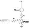
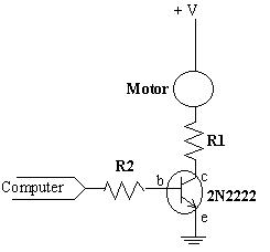
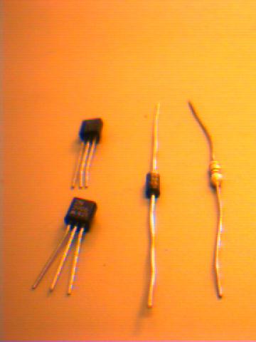
The simplest way to control a dc motor is thru the use of a transistor.
Transistors act like switches. In the first figure, R1 is a 1 kilo-ohms
resistance, and R2 is any small resistance (10-300 ohms). Q1 is a very common
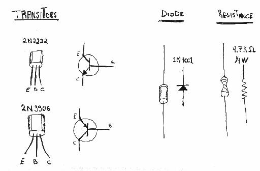
type of transistor: a 2N2222. See part
list for a drawing of these, and this
for a picture. A transistor costs no more than 50 cents.

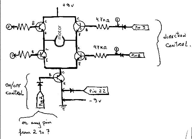
In order to control bi-directional a motor (ON/OFF, and clockwise or
counterclockwise), a H-type circuit is needed. In the second picture, if both
upper left and lower right transistors are ON, the current will flow through
the motor from left to right, yielding a CW rotation.
Trouble is that there is a lost of power. I have not been able to sink more
than 500 mA through the motor in the H circuit. It is enough for small motors,
but not for the Lego-type motors who need a full 1 ampere of
current.
One alternative is to replace transistors with power-mofset. I haven't try,
but you might look at MOSFET
H-Bridge Schematic & Theory of Operation for more. Another alternative
that I explored in tutorial 2 is to use a mechanical switch to control the
direction of motion. Relays are electro-magnetic switch that can be controlled
easily with a transistor. Since the current is independent of the
transistor-magnet circuit, there is no lost of power.
For more on stepper motors, see Controllers
for servos motors with commercial drivers.
-
Choosing communication port
Choosing a mean of communication. Our computer needs to communicate to the
controller. The two likely methods are to use the ports available. There is
two kind of port. The parallel port (or printer port) is easy to program, but
has a limited capacity at any given time. In the best case, it can only output
8 bits of information, and can input from sensor 8 bits.
-
Choosing the kind of sensors you need.
There is a large variety in sensors, ranging from electronic thermometer to
pressure sensors. The simplest kind is the on/off sensors. When pressure is
applied, the switch turns on. One bit of information is enough per
sensor.

Programming a computer-controlled robot can involves many embedded
programs, or layers.
-
Basic moves / reading sensors
The lowest level is basically a software that can send command to the
controller, or receive data from the sensors. Otherwise said, it is a
program that operates your parallel port (or serial port, whichever is
connected to your controller), using meaningful commands such as TURN(30),
START(2), IS_ON?(1), etc. It is best seen as a repository of what can be
done by your robot. In WINDOWS, a good programming habit is to place these
commands as functions in a library. Commands in libraries are retrieved
whenever needed by any other program (higher layers). This type of library
is called DLL (Dynamically linked library); the resulting file have to be
located in the \WINDOWS or \WINDOWS\SYSTEM directory.
- Most compilers can produces DLL. For example, in Pascal, you start
with the word library LEGO; then type in the functions needed.
If you want to be able to use functions in library, you have to declare them
external. For example, in Visual Basic, you write in the (general
declaration) section: Function ABOUT: integer EXTERNAL "LEGO"
where Lego is the name of the DLL file.
The instruction you are likely to use in your library is PORT. That
instruction can send or receive data from a computer parallel port. For
example (in QBasic):
PORT &H3F8, 9
sends 00001001 to the first eight bits of the parallel port.
With a serial port, use file access procedure OPEN:
OPEN "COM1:9600,N,8,1" FOR RANDOM AS #1
PRINT #1,9
sends 00001001 to the COM1 port, at a speed of 9600.
In my LEGO.DLL (see that),
I programmed the procedure START(x) that light the motor number x using
these procedures (in Pascal):
function START (x: motor_no): integer; export;
{light the motor x; use STOP to stop it}
var mask, i: byte;
begin
if (x<1)or(x7) then START := -4
else
if base <= 0 then START := -3
else begin
mask:=1;
for i:=1 to x-1 do mask:= mask*2;
motor_state := motor_state or mask;
output_motor_state;
START:=0;
end;
end;
procedure output_motor_state;
{note that the last bit of port[base] is for the reverse of direction pin 9}
var mask: byte;
begin
port[base]:= motor_state;
end;
base is the address of the port, determined by the INIT procedure (not
shown here). If an error occurs, that is, if the function does not return
zero, use ERROR(nbre returned). ERROR is available in the DLL, and contains
a list of all the possible error with an explanation. The variable
MOTOR_STATE keeps tracks (in binary) of all motor states. For example,
00000001 means the last motor is ON while all other are OFF.
-
Sending commands/receiving data
The first layer is only a list of what can possibly be done with your robot.
Now we need to send specific commands to your robot.
Commands can be very simple, such as "Start motor 3 now", or
more complex, such as "Start motor 3, wait 5 seconds, start motor
2, and when sensor 2 gets on, stop all moves."
The VBASIC interface that I proposed in another page is an example which can
send only simple commands. A better interface would accept commands such as
"Turn motor 3 for x seconds" or "Turn motor 3 until sensor 2
gets on".
-
Constraint control
Not all moves are safe for the health of your robots. For example, turning
the arm to the left for an indefinite time is risky if your arm cannot do
more than 360 degree turns (and most arms can not do that much).
In order to avoid wreckage, your robot should know things about its
limitations. These are called constraints. Example of constraints are:
If the base is turning for more than 5 seconds, then you ought to stop
turning the base.
If the sensor in the hand feel excessive pressure, you ought to stop
grasping. Constraints are easily expressed in the form "If … you ought to
…". It is like a watching device that monitors the commands sent
by the layer B so that no crash occurs. This layer should never be seen
but always be on.
-
Artificial intelligence
Here I refer to giving some brain to your computer-robot. I can think of
two kind, both related to machine learning. The first is learning new higher
level commands, such as PICK, which is a string of various low-level
commands. This learning could be performed by noting that some strings are
common, and thus the machine should be asking the human a new name for it.
The second type of learning is learning the constraints the robot must
obey. This could be achieved by sending signals that could be termed
"Pain" and let the robot figure out what sensors or movement
started it.
|