
|
|
Site map :
Last upgrade to the site:
There has been
This is an unofficial LEGO® web site. Copyright 1996, 2000, Denis Cousineau
|
Relays are switch that can be turned on and off using electricity (relays cost ~1.50$). They are electromagnetic switch, which means that a magnet is responsible for turning the switch. Relays can drive a voltage +V that is as large as you need (using the appropriate relay, of course) will being controlled by a power +Vcc that can be small (usually 5 V). This mean that with a computer (working on 5 V, with very small power ~.05 Ampere, you can control a motor of 9 V, 1 ampere, like the Lego motors).
The previous diagram illustrates the different parts of the DPDT relays. The all have 8 pins, two on one side and the remaining 6 on the other side. Normally, a power voltage is applied to the pin labeled +V, and the opposite pin is connected to the ground (not pictured here). This current will get out thru pin a, can be send to a load (such as a motor), and must be send to c so that it can connect with ground. In this situation, pins b and d are passive. If current is applied to +Vcc and the opposite pin is connected to ground, things are reversed: a and c become passive, will b and d drive the +V power. Therefore with this kind of relay, you can choose to either power one appliance or another.
For a test: Using a power source (such as a Lego battery pack, or a wall transformer –be sure that the voltage is smaller than 10 volts), connect one of the pin on one side of the relay to the positive end, and the facing pin the other contact. Immediately, you should here an audible click: the relay has just switch from a-c to b-d which mean it is working properly. If not, reverse the connections.
There exist a large number of transistor, but they all are either NPN or PNP. In the designs that will follow, it is important that you use NPN transistors, such as the 2N2222 (Transistors costs ~0.50$). Transistors have three pins, labeled on the case: c (collector), b (base) and e (emitter). The transistor must always be placed *after* the load, so that pin e is link to the ground. The load can be merely anything: a light, a motor… that normally works with a voltage of +Vcc (DC). But instead of connecting the load to the ground, you connect it to the c pin of the transistor. The b pin of transistor is used to turn on or off the load, by applying a very small current. The R represents a resistor. It is used as a protection if you use a computer to send a small current (in this case, it should be a 1 kilo-ohm resistor). When the transistor turns on, you won’t hear a click, since it is a "solid-state" device (which means it is not a mechanical device).
For a test: As a load, we can use a led (a small light). It need to be connected serially with a 3.3 kilo-ohm resistor; the resistor can be before or after the led, it does not matter). The +Vcc power voltage can be two batteries of 1.5 volts, connected serially. Now, connect the pin 2 of your printer port LPT1: (be sure to identify the correct pin, most of the time, pins are numbered on the printer cable) to the resistor R; also connect the pin 25 to the ground (remember: all ground must be connected together). If you run the program above, the led should light, and then be turned off. In the above program, 378 is the address of your printer port (you can see it when you start your computer, in the diagnostic box following the memory test).
The H-Bridge circuitBasically, the direction of motion of a motor depends on the way it is connected. If the right pole is connected to +Vcc, the motor will turn clockwise, while the opposite will occur if +Vcc is connected to the left pole. A H-bridge is the superposition of the two at the same time. In the following diagram, if switch a and c are turn on, the motor will turn clockwise, while if b and d are turned on, the rotation will be counter clockwise. If both (a and d) or (b and c) are on, the motor will not turn since the current will flow directly from Vcc to ground (electricity always tries to avoid load).
Putting it all togetherControlling the position of the relayThe first thing is to be able to trigger the relay using the computer. You can use pin number 2. +Vcc must be a power source compatible with the relay specification. If thing works fine, you should be able to hear the thick when relay turns on.
Making an H-bridge circuit with a DPDT relayThe DPTP relay is in fact a very convenient way of implementing an H-bridge. When the relay is not connected, a and c are conducting current, therefore, +V makes the motor turning clockwise. If the relay is activated, b and d are conducting, and try it, the motor will turn counter clockwise. The only way current from b can return to ground is to pass through the load (the motor). The nice thing is that (a and d) or (b and c) cannot be both on at the same time.
Turning on and off the motor.The motor in the previous design is either turning clockwise or counter clock wise, but never stop. We will consider the H-bridge as a load, and use a transistor to turn this load on or off. For that, we need another computer pin, for example, pin 3 (use PORT &H378, 2 to turn it on, and PORT &H378, 2+1 for both pin 2 and 3 at the same time).
The final schematic and physical implementationThe schematicIn order to realize an electronic project, you need to go through 4 steps: making a schematic of the circuit, that is an abstract representation of the pieces and how they are connected together. The above diagrams are all schematic. Next, you need to device how the pieces will be actually connected (that is physically). You have to think both of the component placement on the one side of the circuit board, and the traces (the connections) on the other side of the board. Finally, you have to actually make the circuit. This is certainly the most difficult part, the one that require the largest amount of patience.
The physical planThe following plan is one of the possible plan we can come with. I tried to make it narrow, so that I can put multiple instance of this circuit, in order to control multiple motors. The direction span on a long trace, so that it can control the direction of the other motors as well. This is not a necessary restriction though.
Components Side
Trace Side
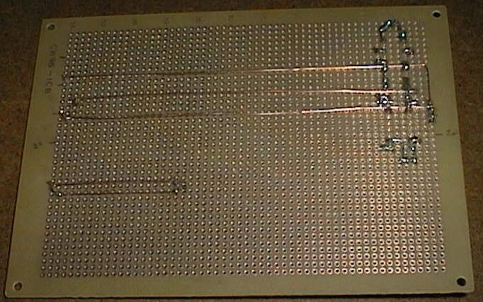
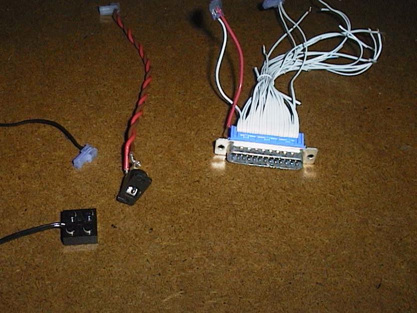
The resultIn the following pictures, I used a different plan. Instead of soldering the pieces directly on the board, I soldered 18-pin sockets, and the pieces are pined on the sockets. It makes replacement of pieces easier, in case a transistor is burned (this sometimes occurs if you short-circuit two wires – you know by the odor).
With the program described elsewhere in this site, you are able to control up to seven Lego motors. | ||||||||||||||||||||||||||||||||||||||||||||
|